


Intelino is a smart train system designed for children and educators to engage in interactive play and learning. It combines physical trains with digital technology, allowing users to control and program the trains using special code tiles. In this tutorial, you can follow my steps as I recreate my first 3D printable design for Intelino using Tinkercad, a free Computer-aided Design (CAD) software.
This project is well-suited for 3D printing because the Intelino code tiles are easy to misplace and 3D printing a replacement takes under 10 minutes. Below is a video walkthrough of the entire CAD process, a list of materials with links, and step-by-step instructions to help you follow along!
Materials:
- 3D Printing Supplies:
- 3D printer (Creality Ender 3 S1)
- 3D printing filament (choose a preexisting Intelino tile color)
- Slicing software (Cura, Creality Slicer)
- Tinkercad Account
- Computer with Internet Access
- Measuring Tools (calipers)
Video CAD Demonstration:
Step-by-step Instructions:
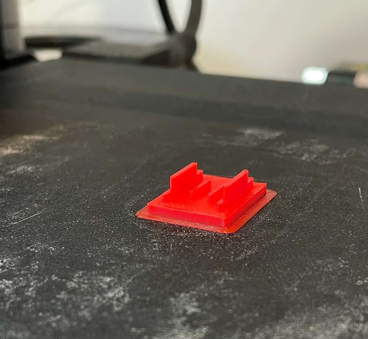
Before you begin to CAD the Intelino code tile, take a second and examine the photo below. If you have an Intelino tile on hand, use calipers or another accurate measurement device to obtain the tiles dimensions (I also include dimensions below, so don’t worry if you are unable to take your own measurements). After taking a look at the tile, try to imagine the steps you might take to design it in Tinkercad.
.avif)
- Set Up Your Tinkercad Workspace
- Log into Tinkercad or Create an Account
- Create a New Design
- Click on the “Create new design” button to start a new project
- Design the Base of the Tile
- Add a Box Shape
- Drag a "Box" shape from the shapes menu onto the workplane
- Set the dimensions of the box
- Width: .63in
- Length: .80in
- Height: .08in
- Add a Box Shape
- Create the Base of the Tabs on the Base of the Tile
- Add another box shape
- Set the dimensions of the box
- Width: .04in
- Length: .63in
- Height: .06in
- Set the dimensions of the box
- Duplicate the dimensioned box
- Use the duplication shortcut (Ctrl+D or Command+D) to create copies
- Position new geometry
- Place both boxes on the top surface of the base of the tile (use the W key for help with alignment)
- Align the boxes so they are parallel and in the vertical and horizontal center of the base of the tile
- Insure a .47in distance between the outside edges of the boxes (use the ruler tool for help defining this measurement)
- Add another box shape
- Add Tabs
- Add a new box shape (this will be our tab)some text
- Set the dimensions of the tab
- Width: .04in
- Length: .40in
- Height: .10in
- Set the dimensions of the tab
- Align this tab with one of the previous tab bases
- Center and position it on the top plane of the box beneath it
- Duplicate
- Duplicate the tab you just created and position it on the remaining tab base
- Add a new box shape (this will be our tab)some text
- Add Support Geometry
- Add a new box shape
- Set the dimensions of the box
- Width: .04in
- Length: .32in
- Height: .05in
- Set the dimensions of the box
- Duplicate
- Duplicate the tab you just created and position it on the remaining tab base
- Align the support boxes
- Align the boxes to there is a .18in gap between the outside edges of the boxes (use the ruler tool again for help defining this measurement)
- Group the boxes
- Vertically and horizontally center the grouped boxes on the base of the tile
- Add a new box shape
- 3D Printing your Intelino Tile!
- Export the Design
- Once you are finished with your design, click on the “Export” button.
- Choose “.STL” as the file format to prepare your design for 3D printing.
- Download the STL File
- Save the STL file to your computer. This file can now be used with a 3D printer to create your Intelino train code tile
- Prepare the Printer
- Import the STL file into your 3D printer's slicing software (e.g., Cura).
- Adjust the print settings as needed for your 3D printer and filament type
- Print the Tile
- Start the 3D printing process and wait for your Intelino train code tile to be printed!
- Export the Design
Project Examples
Have a solution to this challenge you want to share? Take a photo or video of your prototype, post it on social media, and don’t forget to tag us @fluxspace_io


