


Another element of our preparation for PETE&C was to construct a real eye catcher—something you would see from across the room and immediately think “I need to see what that’s all about.” In conversations last year, we threw around the idea of building a claw machine, we bought a kit off AliExpress, but never got around to the construction. This year, we dug back through the closet and got to work early. Now, we’d be remiss to claim we know exactly what our builds are going to look like when we’re finished, but this machine in particular shocked me with how many times it changed forms.
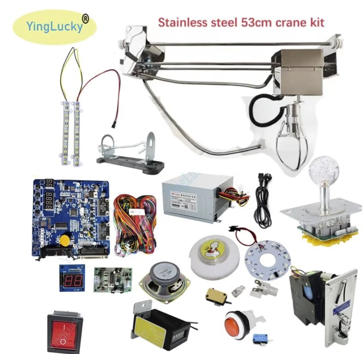
To start, we unboxed the AliExpress kit and inspected the parts. The basics all seemed to be present, but we didn’t have any instructions! (or a case for that matter… a problem for a later day) As much as I’d love it if four years of engineering schooling gave you some forbidden knowledge regarding the design and assembly of all machines, it unfortunately does not. It does, however, give you the confidence to plug things in and see what happens—and that’s exactly what we did.
With everything hooked up in a seemingly logical fashion, it was time for the moment of truth. We plugged it in, lights flashed on, and the machine began trying to home itself. Much like 3D printers, claw machines have limit switches at the edges of the gantry that it uses to know where the prize drop is. Except for one thing, the LED display read “HOME ERROR,” indicating that the machine failed to home. We kept fidgeting with it for a bit and after a few attempts, we plugged it in and smelled something funky. I recognized it right away: burning electronics. Something was getting too much power. We ripped the plug out of the wall and searched for the source of the smell, and sure enough, we found a part of the mainboard that had been burnt out.
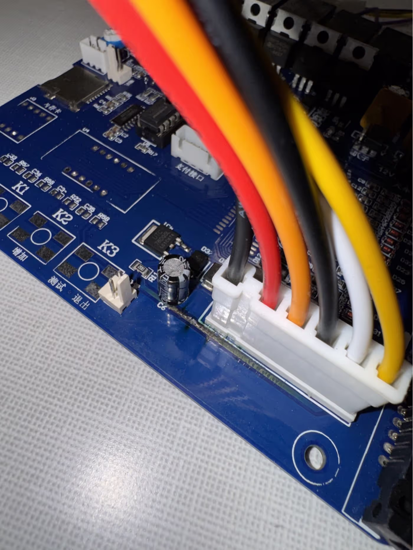
In a circuit board like the mainboard of a claw machine, there's a bunch of tiny wires under the surface of the board that are routed by machines (hence the name printed circuit board or PCB). Those tiny wires, often called traces, have a thickness that’s determined by how much power you want to flow through them. If you try to pump too much power through it, you’ll begin to generate heat, causing the wire to expand, break out of board, and destroy itself. Our mainboard was busted.
We searched far and wide for some form of support and ended up on the phone with customer service over at HollandComputers. It turns out there’s a few different designs for claw machine circuitry, and we chose one that was a little more niche than others. Determined to deliver a claw machine for this conference, we shifted our search towards a replacement kit (ideally one with instructions). Delighted by my interactions with their customer service and equipped with newfound knowledge about claw machine quality, I landed on a claw machine kit from the same folks.
.avif)
This thing had it all: a manual. The only drawback with this kit was that it did not come with a coin slot. The particularly crafty reader may think at this point that that’s no big deal and that we could just hook up the same pins to a button. Clever, but not entirely correct. It turns out that some versions these machines only really hear signals from electronic coin comparators (another gem of advice dropped to us from the customer service at HollandComputers. Seriously, can’t thank these guys enough for the help they provided, specifically Chris). Fortunately, we had an extra coin comparator from the previous kit. We hooked the whole thing up, propped it up on chairs, and plugged it in.
.avif)
Despite my doubts and fears from the previous claw, this thing worked perfectly! Now we were left with 4 days and an entire frame to design and build. Fortunately, the claw kit left us relatively unconstrained. The only specification was that we needed two ½” grounding rods 28 inches apart from each other. We began with some drawings and conversations about what the machine would look like. I wanted to CAD the whole thing, but with our time constraints and the rate at which our design was changing shape, it wasn’t feasible. We got to work quickly.
.avif)
After a day or so, the machine had taken its basic shape and function, consisting of nothing but a square top with four legs, but it worked. The following days consisted of more trips to Home Depot, a couple design reevaluations, and some last minute pivots/touch-ups. One of the mention-worthy additions is the design and 3D printing of the mounting brackets for the joystick, button, LED display, and speaker. We needed these things quickly, but that wasn’t a major problem since our new Raise Pro3 has the upgrade that lets it print at 300mm/sec. I drew up these designs in Onshape and processed them further using nTop. Here’s the CAD and the final part.
.avif)
.avif)
Project Examples
Have a solution to this challenge you want to share? Take a photo or video of your prototype, post it on social media, and don’t forget to tag us @fluxspace_io


